
Monitoring of electrocardiogram (ECG) for augmented leads aVF,aVL and aVR.
Monitoring of electrocardiogram (ECG) for augmented leads aVF,aVL and aVR.
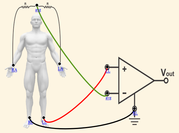
1. For Lead aVF
STEP 1 : Make all the Correct Connections.
1. Connect Left Leg Electrode (LL) of human to the positive terminal (LL) of op-amp circuit.
2. Connect (avg) point of right arm electrode and left arm electrode of human to the negative terminal (avg) of op-amp circuit.
3. Connect Right Leg Electrode (RL) of human to the ground terminal (RL) of op-amp circuit.
STEP 2 : Click on check button to check for Correct Connections.
STEP 3 : If Connections are not correct click on reset button for reset connections.
STEP 4 : If Connections are correct click on play/pause button to see waveform for lead aVF.
STEP 5 : Click on waveform tab for data calculations and BPM measurement .
STEP 6 : Click on print button to save the observations.
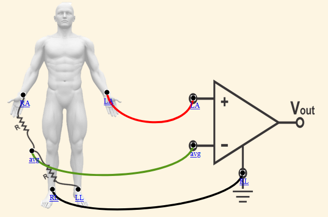
2. For Lead aVL
STEP 1 : Make all the Correct Connections.
1. Connect Left Arm Electrode (LA) of human to the positive terminal (LA) of op-amp circuit.
2. Connect (avg) point of right arm electrode and left leg electrode of human to the negative terminal (avg) of op-amp circuit.
3. Connect Right Leg Electrode (RL) of human to the ground terminal (RL) of op-amp circuit.
STEP 2 : Click on check button to check for Correct Connections.
STEP 3 : If Connections are not correct click on reset button for reset connections.
STEP 4 : If Connections are correct click on play/pause button to see waveform for lead aVL.
STEP 5 : Click on waveform tab for data calculations and BPM measurement .
STEP 6 : Click on print button to save the observations.
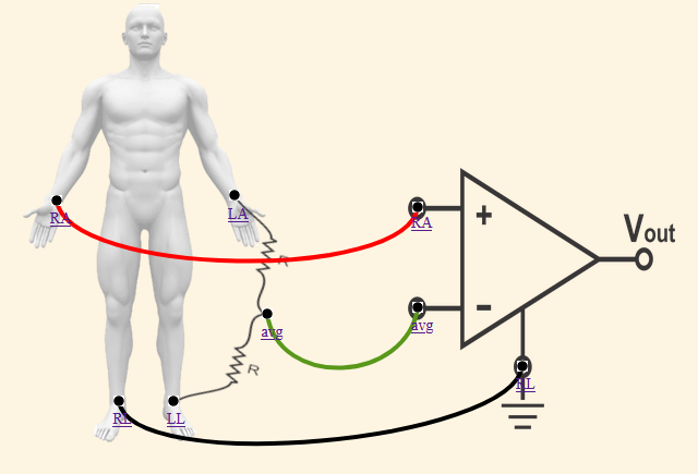
3. For Lead aVR
STEP 1 : Make all the Correct Connections.
1. Connect Right Arm Electrode (RA) of human to the positive terminal (RA) of op-amp circuit.
2. Connect (avg) point of left arm electrode and left leg electrode of human to the negative terminal (avg) of op-amp circuit.
3. Connect Right Leg Electrode (RL) of human to the ground terminal (RL) of op-amp circuit.
STEP 2 : Click on check button to check for Correct Connections.
STEP 3 : If Connections are not correct click on reset button for reset connections.
STEP 4 : If Connections are correct click on play/pause button to see waveform for lead aVR.
STEP 5 : Click on waveform tab for data calculations and BPM measurement .
STEP 6 : Click on print button to save the observations.